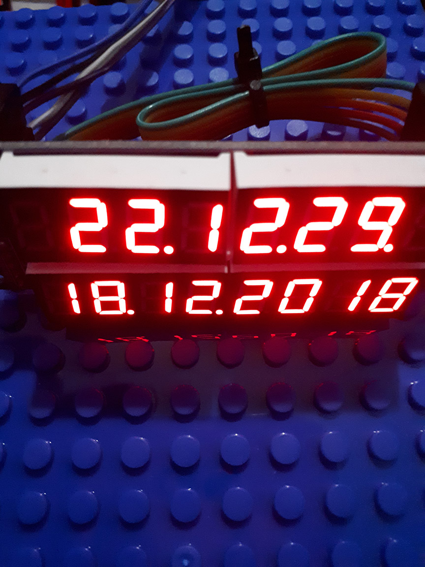
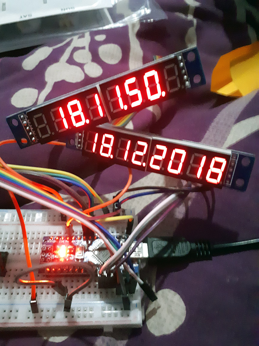
This is a small project that I created using MAX7219 8 Digit 7 Segment Displays to create a clock that shows the date and time. I used an DS1307 Real Time Clock for keeping time, and an Arduino Nano to bring it all together on a small breadboard (for now).
Components Required
MAX7219 8 digit 7 segment display x 2
TinyRTC I2C DS1307 RTC Module
Arduino Nano (can also be used on an Uno)
Breadboard
Connecting Wires

TinyRTC Issues
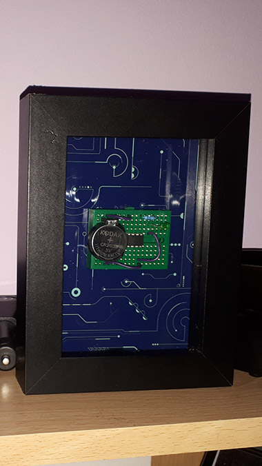
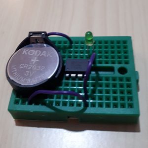
I ordered a TinyRTC I2C module from eBay, however, it did not come with a rechargeable LIM2032 battery but a standard CR2032 non rechargeable lithium battery. As the TinyRTC I2C DS1307 module has a charging circuit for charging lithium cells, this needed to be modified so that it would not charge a non rechargeable cell. I’d like to credit the website brainy-bits.com for the details below on how to modify the module to remove the charging circuitry and allow me to use the module with a standard CR2032 battery.
Modifying the TinyRTC
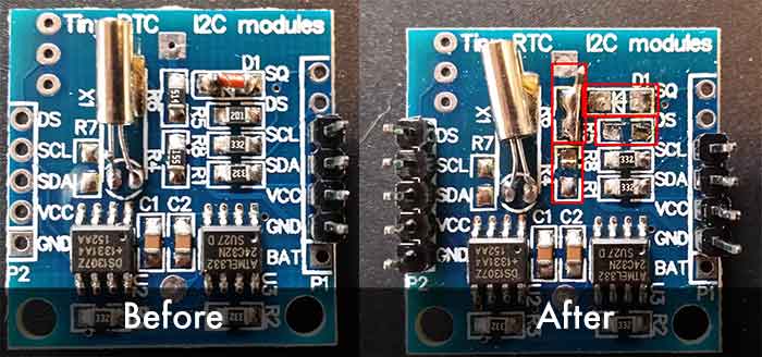
You need to remove the Diode at D1 and both the resistors at R6 and R4. You then need to create a solder (or wire bridge) between the pads of R6. If you need further advice with this, check out their original article which I found this information from here.
Now that we have modified the DS1307, we can attach it to the Arduino on the SPI headers, which on the Nano is located at A5 for SCL and A4 for SDA. Then you need to connect VCC to +5 Volt and GND to GND.
Attaching the MAX7219 strips
Then to attach our first MAX7219 with the following connections: Pin 9 is connected to the DataIn, Pin 8 is connected to the CLK and pin 7 is connected to LOAD. VCC goes to +5 Volt and GND to GND.
Our second MAX7219 display can connect to the first one, making sure that DataOut on the first module is connected to DataIn on the second module and that LOAD, CLK, VCC and GND are connected to each other.
Setting The Time
Now your circuit is built, we need to set the time on the DS1307. Once you have installed the required libraries (linked below), you can open the example sketch from the DS1307RTC for SetTime.
However, I have found that this sets the time 7 seconds too slow. This is because it uses the time that the program was compiled as its reference for time, and takes a few seconds to upload to the Arduino nano. This modified sketch won’t function correctly if you compile within the last 7 seconds of a minute, however this can be adjusted by changing the DEFINE Offset 7 below if you find that this isn’t correct for your needs.
Libraries
Time Library – https://github.com/PaulStoffregen/Time or download here
DS1307RTC Library – https://github.com/PaulStoffregen/DS1307RTC or download here
LedControl Library – https://github.com/wayoda/LedControl or download here
SetTime_with_Offset.ino
/*   FILENAME: SetTime_with_Offset.ino
*   AUTHOR(s): Jessica at AccessiblePixel.com
*   CONTACT: media@accessiblepixel.com
*   LICENSE:
*
*   This program is free software: you can redistribute it and/or modify
*   it under the terms of the GNU General Public License as published by
*   the Free Software Foundation, either version 3 of the License, or
*   (at your option) any later version.
*
*   This program is distributed in the hope that it will be useful,
*   but WITHOUT ANY WARRANTY; without even the implied warranty of
*   MERCHANTABILITY or FITNESS FOR A PARTICULAR PURPOSE.  See the
*   GNU General Public License for more details.
*
*   You should have received a copy of the GNU General Public License
*   along with this program.  If not, see <https://www.gnu.org/licenses/>.
*/
#include <Wire.h>
#include <TimeLib.h>
#include <DS1307RTC.h>
#define OFFSET 7 // Offset for Adding Seconds
const char *monthName[12] = {
"Jan", "Feb", "Mar", "Apr", "May", "Jun",
"Jul", "Aug", "Sep", "Oct", "Nov", "Dec"
};
tmElements_t tm;
void setup() {
bool parse=false;
bool config=false;
// get the date and time the compiler was run
if (getDate(__DATE__) && getTime(__TIME__)) {
parse = true;
// and configure the RTC with this info
if (RTC.write(tm)) {
config = true;
}
}
Serial.begin(9600);
while (!Serial) ; // wait for Arduino Serial Monitor
delay(200);
if (parse && config) {
Serial.print("DS1307 configured Time=");
Serial.print(tm.Hour);
Serial.print(tm.Minute);
Serial.print(tm.Second);
Serial.print(", Date=");
Serial.println(__DATE__);
} else if (parse) {
Serial.println("DS1307 Communication Error :-{");
Serial.println("Please check your circuitry");
} else {
Serial.print("Could not parse info from the compiler, Time=\"");
Serial.print(__TIME__);
Serial.print("\", Date=\"");
Serial.print(__DATE__);
Serial.println("\"");
}
}
void loop() {
}
bool getTime(const char *str)
{
int Hour, Min, Sec;
if (sscanf(str, "%d:%d:%d", &Hour, &Min, &Sec) != 3) return false;
tm.Hour = Hour;
tm.Minute = Min;
tm.Second = Sec;
tm.Second = tm.Second + OFFSET;
return true;
}
bool getDate(const char *str)
{
char Month[12];
int Day, Year;
uint8_t monthIndex;
if (sscanf(str, "%s %d %d", Month, &Day, &Year) != 3) return false;
for (monthIndex = 0; monthIndex < 12; monthIndex++) {
if (strcmp(Month, monthName[monthIndex]) == 0) break;
}
if (monthIndex >= 12) return false;
tm.Day = Day;
tm.Month = monthIndex + 1;
tm.Year = CalendarYrToTm(Year);
return true;
}
Now if you open your serial console, you should see that it has set the time correctly.
Finally you can upload the following code (after installing the libraries linked above) to get your clock up and running.
MAX7219_LED_Clock.ino
/*   FILENAME: MAX7219_LED_Clock.ino
*   AUTHOR(s): Jessica at AccessiblePixel.com
*   CONTACT: media@accessiblepixel.com
*   LICENSE:
*
*   This program is free software: you can redistribute it and/or modify
*   it under the terms of the GNU General Public License as published by
*   the Free Software Foundation, either version 3 of the License, or
*   (at your option) any later version.
*
*   This program is distributed in the hope that it will be useful,
*   but WITHOUT ANY WARRANTY; without even the implied warranty of
*   MERCHANTABILITY or FITNESS FOR A PARTICULAR PURPOSE.  See the
*   GNU General Public License for more details.
*
*   You should have received a copy of the GNU General Public License
*   along with this program.  If not, see <https://www.gnu.org/licenses/>.
*/
//
// Include Libraries
//
#include <Time.h>  // Time Manipulation Library
#include <DS1307RTC.h>  // DS1307 RTC Library
#include "LedControl.h" // MAX72XX Library
//
// Defines
//
#define TOTAL_STRIPS 2 // Set How Many Strips of MAX7219 7 Segment Displays
#define DATAIN 9 // pin 9 is connected to the DataIn
#define CLK 8 // pin 8 is connected to the CLK
#define LOAD 7 // pin 7 is connected to LOAD
//
// Start LedControl MAX7219 Library
//
LedControl lc=LedControl(DATAIN,CLK,LOAD,TOTAL_STRIPS);
//
// Set Variables
//
int year4digit;  // 4 digit year
//
// Setup (Run Once)
//
void setup() {
//
// The MAX7219 needs waking up as it is in power-saving mode on startup.
// This will wake all connected displays.
//
for (int loop = 0; loop < (TOTAL_STRIPS); loop++) {
lc.shutdown(loop,false);
// Set the brightness to a medium value
lc.setIntensity(loop,4);
// Clear the display
lc.clearDisplay(loop);
}
}
//
// Loop (Run Forever)
//
void loop() {
//
// Get data from the DS1307 RTC
//
tmElements_t tm;
if (RTC.read(tm)) {
year4digit = tm.Year + 1970;  // Create an accurate 4 digit year variable
}
//
// Get Single Digits from each number using modulus
//
// Quick Guide to Modulus with Arduino
// Given the number 2018:
// How to get:
// 8 is 2018 % 10
// 1 is 2018 / 10 % 10
// 0 is 2018 / 100 % 10
// 2 is 2018 / 1000 % 10
int firsthourdigit = tm.Hour /10 % 10;
int secondhourdigit = tm.Hour % 10;
int firstminutedigit = tm.Minute /10 % 10;
int secondminutedigit = tm.Minute % 10;
int firstseconddigit = tm.Second /10 % 10;
int secondseconddigit = tm.Second % 10;
int firstdigitday = tm.Day /10 % 10;
int seconddigitday = tm.Day %10;
int firstdigitmonth = tm.Month /10 % 10;
int seconddigitmonth = tm.Month % 10;
int firstdigityear = year4digit / 1000 % 10;
int seconddigityear = year4digit / 100 % 10;
int thirddigityear = year4digit / 10 % 10;
int fourthdigityear = year4digit %10;
//
// Output the digits
//
//
// First Display (as wired) displaying Time: HH.MM.SS format
//
lc.setDigit(0,6,firsthourdigit,false);    // First Hour Digit     2
lc.setDigit(0,5,secondhourdigit,true);    // Second Hour Digit    1 (with a .)
lc.setDigit(0,4,firstminutedigit,false);  // First Minute Digit   2
lc.setDigit(0,3,secondminutedigit,true);  // Second Minute Digit  3 (with a .)
lc.setDigit(0,2,firstseconddigit,false);  // First Second Digit   3
lc.setDigit(0,1,secondseconddigit,true);  // Second Second Digit  4 (with a .)
//
// Second Display (as wired) displaying Date: DD.MM.YYYY format.
//
lc.setDigit(1,7,firstdigitday,false);     // First Day Digit      1
lc.setDigit(1,6,seconddigitday,true);     // Second Day Digit     8 (with a .)
lc.setDigit(1,5,firstdigitmonth,false);   // First Month Digit    1
lc.setDigit(1,4,seconddigitmonth,true);   // Second Month Digit   2 (with a .)
lc.setDigit(1,3,firstdigityear,false);    // First Year Digit     2
lc.setDigit(1,2,seconddigityear,false);   // Second Year Digit    0
lc.setDigit(1,1,thirddigityear,false);    // Third Year Digit     1
lc.setDigit(1,0,fourthdigityear,false);   // Fourth Year Digit    8
delay(250);
}