ATTiny85 Art Piece and first circuit development

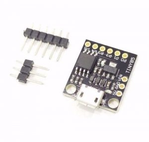
This is the first circuit designed with a stand alone chip that runs the basic blink sketch. It uses an ATTiny85.
To setup the Arduino IDE, there is an excellent guide available at highlowtech.org which also works with the latest version of the Arduino IDE.

ATTiny85 in a small wooden, black frame and circuit background.

Once you have setup a circuit to program the ATTiny85, you can choose how fast the processor runs. Usually you’d want to run it at 8MHz. However, because I am running the piece off a CR2032 lithium cell, power is at a minimum. I read the data-sheet for the ATTiny85 and found that at 8MHz (at 3volt) it uses around 3.5mA and at 1MHz it uses about 0.5mA. So using this I managed to save 3mA of power. The other issue was the LED. This was consuming approximately 15-20mA every time it lit up. So I added a 47k ohm resistor to it, and reduced its power consumption.

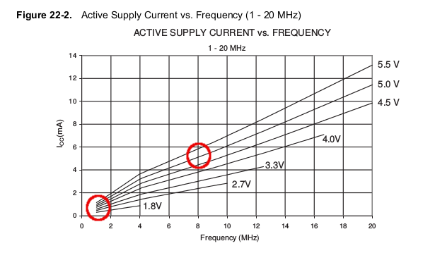
As the average CR2032 cell has 235mA capacity, with the original power consumption the piece would have only lasted about a day. With these power optimisations, it will last at least 17 days before the cell needs replacing.

The first revision of the circuit board, before power optimisation

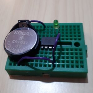
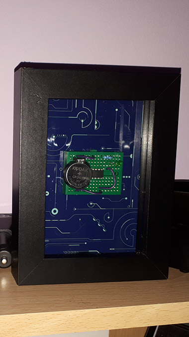
The circuit has been placed on a small green breadboard, a CR2032 cell holder, a CR2032 cell, connecting wire, a 47K ohm resistor and the ATTiny85 chip. I also printed a circuit background for the piece.

The code the ATTiny85 is running is simple, it’s just a modified version of the default blink sketch.

void setup() {
pinMode(0, OUTPUT);
}
void loop() {
digitalWrite(0, HIGH);
delay(1000);
digitalWrite(0, LOW);
delay(1000);
}

More Microcontrollers – Digispark ATTiny85

Browsing eBay for additional Arduino hardware, I came across a Digispark ATTiny85 clone for £1.99 shipped from the UK. You can get them cheaper in bulk from China though. I did some searching on YouTube to see the kind of things that this development board is capable of. I initially searched for compatibility with the WS2812 LED strings, and yes – there’s someone running the Adafrult Neopixel Library and the srandtest sketch on the Digispark ATTiny85 🙂

These tiny boards can also be used for many other projects – including emulating a USB Keyboard. I might make something to switch input over on the future video recordings 🙂

Here are some specifications:

  • 16.5mHz Microcontroller
  • Power via USB or external source – 5v or 7-35v (Recommend 12v if 5v not available)
  • On-board 500ma 5v regulator
  • 6 I/O Pins (2 of which are used for USB port only if your program uses the USB port, otherwise all 6 are available)
  • 8k Flash Memory (~6k free after bootloader)
  • I2C and SPI (via USI)
  • PWM on 3 pins (more is possible via software PWM)
  • ADC on 4 pins
  • Power LED and Test/Status LED

One thing I quite like is the built in voltage regulator, this will come handy for tiny embedded projects!

There are some caveats to be aware of using this board though. There is no reverse voltage protection, so applying GND and +5 the wrong way around will almost certainly damage the board so perhaps a Diode would be helpful here or a MOSFET?

When uploading a sketch, you have to unplug and re-plug the device to enter programming mode (which the device stays in for 5000ms) then it will run whatever sketch you have uploaded to it.

I’m looking forward to testing this hardware out and now I’m just waiting for delivery 🙂

Skip to content