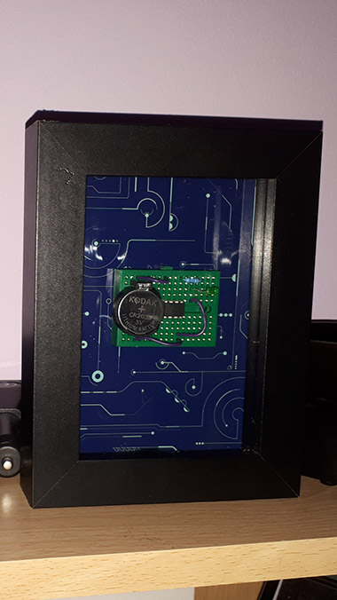
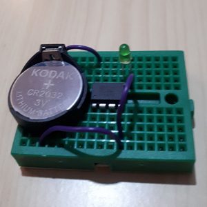
This is the first circuit designed with a stand alone chip that runs the basic blink sketch. It uses an ATTiny85.
To setup the Arduino IDE, there is an excellent guide available at highlowtech.org which also works with the latest version of the Arduino IDE.

Once you have setup a circuit to program the ATTiny85, you can choose how fast the processor runs. Usually you’d want to run it at 8MHz. However, because I am running the piece off a CR2032 lithium cell, power is at a minimum. I read the data-sheet for the ATTiny85 and found that at 8MHz (at 3volt) it uses around 3.5mA and at 1MHz it uses about 0.5mA. So using this I managed to save 3mA of power. The other issue was the LED. This was consuming approximately 15-20mA every time it lit up. So I added a 47k ohm resistor to it, and reduced its power consumption.
![]()
As the average CR2032 cell has 235mA capacity, with the original power consumption the piece would have only lasted about a day. With these power optimisations, it will last at least 17 days before the cell needs replacing.

The circuit has been placed on a small green breadboard, a CR2032 cell holder, a CR2032 cell, connecting wire, a 47K ohm resistor and the ATTiny85 chip. I also printed a circuit background for the piece.
The code the ATTiny85 is running is simple, it’s just a modified version of the default blink sketch.
void setup() {
pinMode(0, OUTPUT);
}
void loop() {
digitalWrite(0, HIGH);
delay(1000);
digitalWrite(0, LOW);
delay(1000);
}
No Comments